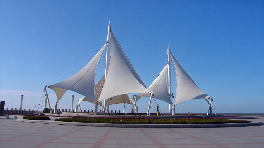
Commercial Tensile Membrane Carport Canopies: The Ultimate Architectural Design Guide
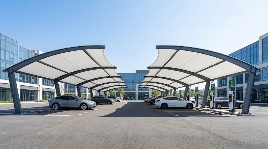
For modern commercial properties, shopping malls, logistics hubs, and corporate office parks, outdoor parking lots are no longer just open asphalt spaces. With the rapid global rise of Electric Vehicles (EVs), businesses are actively seeking modern shading solutions that protect vehicles, integrate solar or charging infrastructure, and enhance property aesthetics.
Traditional heavy steel or concrete carports are increasingly being replaced by tensile membrane carport canopies. These lightweight, large-span fabric structures offer unparalleled design flexibility, lower initial costs, and rapid installation cycles.
If you are an architect, property developer, or procurement manager planning an outdoor parking facility, this comprehensive engineering guide will cover everything you need to know about designing high-performance commercial membrane carports.
1. Key Structural Advantages of Fabric Carports vs. Traditional Roofs
Why are international project managers shifting toward tensile fabric for parking facilities? The answers lie in structural efficiency and space optimization:
- Unmatched Large-Span Capability: Tensile structures can span vast distances with minimal vertical support columns. In a parking lot layout, fewer columns mean more open space, easier vehicle maneuvering, and a 10% to 15% increase in total parking capacity within the same square footage.
- Reduced Foundation and Steel Costs: Because engineered architectural fabrics (like PVDF or PTFE) are lightweight, the dead load on the framework is minimal. This significantly reduces the size and depth of concrete foundations, saving substantial on-site civil engineering costs.
- Rapid On-Site Installation: As an experienced tensile membrane structure manufacturer, we pre-engineer, cut, and weld all steel frames and fabric panels under strict factory conditions. Once shipped to your site, the structure is assembled quickly like a modular system, minimizing business disruption.
2. Selecting the Right Architectural Fabric: PVDF vs. PTFE
Choosing the right membrane material depends on your local climate conditions, project budget, and expected lifespan requirements. The two most widely specified materials for commercial carports are:
| Material Type | Average Lifespan | Key Performance Characteristics |
|---|---|---|
| PVDF-Coated PVC | 10 – 15 Years | Highly cost-effective, excellent flame retardancy, highly flexible for complex geometries, and easy to handle during installation. Highly recommended for standard commercial strip malls and modular parking row projects. |
| PTFE Fiberglass | 25 – 30+ Years | Immune to UV degradation, chemically inert, exceptionally high tensile strength, and completely self-cleaning via rainwater. Ideal for premium corporate headquarters, airports, and high-temperature tropical regions (e.g., Middle East, coastal resorts). |
3. Future-Proofing: Integrating EV Charging Infrastructure
Modern commercial carports are no longer just passive sunshades; they are functional energy hubs. When drafting your carport project, consider these two integration trends:
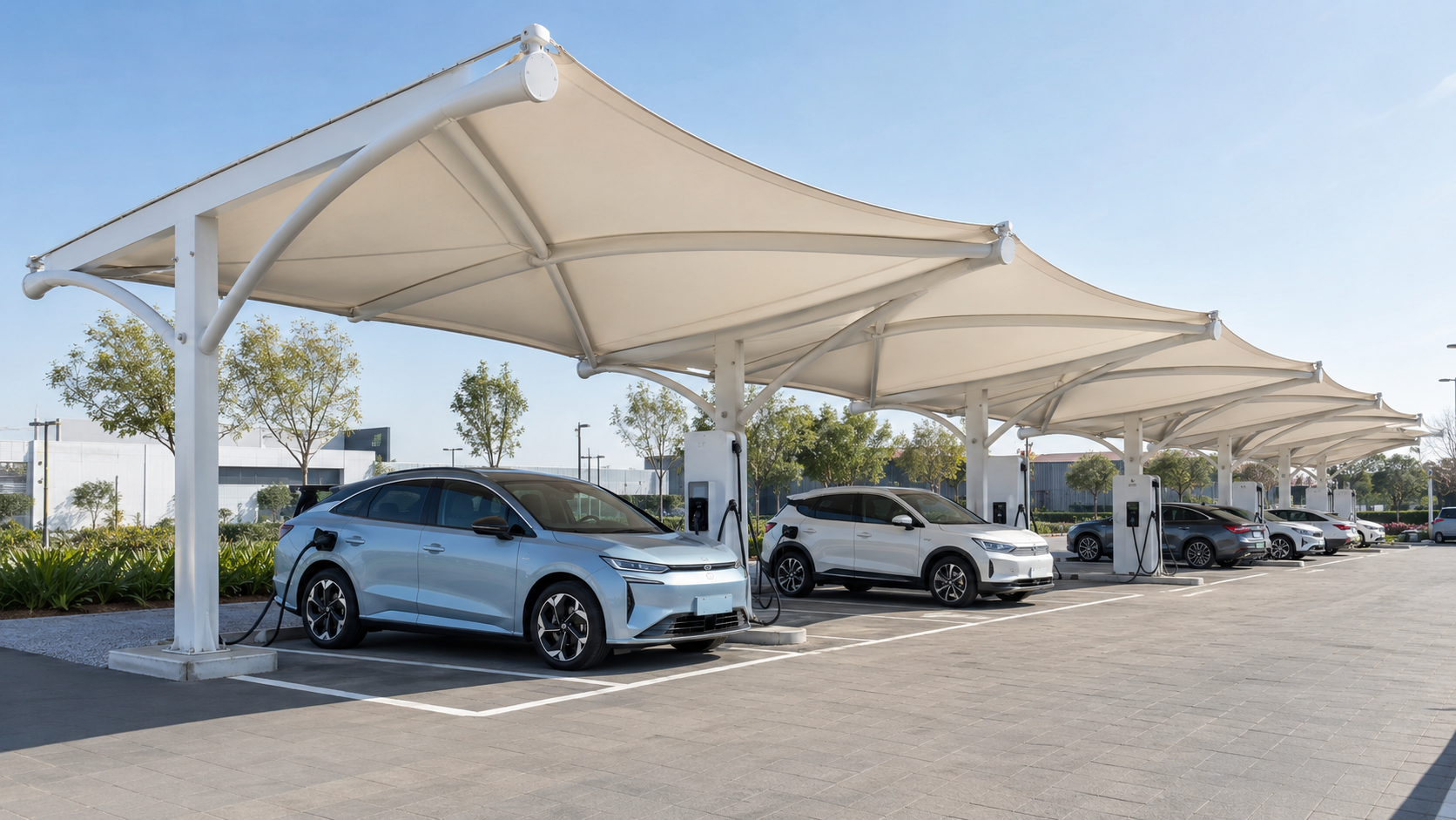
- EV Charging Station Protection: Outdoor charging piles are highly sensitive to extreme heat waves and heavy downpours. A continuous PVDF or PTFE canopy keeps charging stations cool, prevents equipment weathering, and provides a comfortable, dry environment for EV owners while refueling.
- Solar PV Integration: The curved, high-tension steel framework of a modern membrane structure can be engineered to support lightweight flexible solar panels, transforming your parking lot into a clean energy microgrid that powers your commercial buildings.
4. Critical Engineering Considerations Before Fabricating
Before moving from a conceptual rendering to actual factory production, your engineering team must review several site-specific parameters:
- Wind and Snow Load Analysis: Carports are open structures subject to intense wind uplift forces. The structure must be engineered using finite element analysis to withstand local peak wind speeds and snow accumulation codes.
- Water Drainage Layout: High-tension membranes must be designed with precise slopes and curvatures to guide heavy rainwater smoothly into integrated drainage channels within the steel columns, preventing ponding on the fabric surface.
- Anti-Corrosion Steel Treatment: Since carports are fully exposed to outdoor elements, the underlying steel trusses should undergo hot-dip galvanization and premium polyurethane coating to prevent rust and ensure structural safety.
Need a Professional Carport Layout Design or Factory Quote?
Optimizing an outdoor parking layout requires a careful balance between structural safety, aesthetics, and budgeting. At Timi Structure, we specialize in supporting global B2B buyers with complete technical support, from initial CAD layout suggestions to overseas shipping logistics.
Whether you need a massive custom-designed cantilever carport for a commercial plaza or a container load of pre-engineered standard & modular shade structures, our engineering team is here to help.
Contact us today to receive:
- A complimentary parking capacity and structural layout optimization review.
- Wind load and steel structure engineering thickness recommendations.
- A detailed factory-direct fabrication and material cost estimation.
👉 [Click Here to Send Your Parking Lot Dimensions & Get a Custom Carport Proposal]